Dans l’article « L’Arduino et le système de commande numérique DCC », nous avons vu à quoi ressemble la norme DCC.
Dans l’article « Comment piloter trains et accessoires en DCC avec un Arduino (2) », nous avons étudié la bibliothèque CmdrArduino qui se charge de générer les signaux DCC pour nous en tâche de fond.
Dans cet article nous allons utiliser une autre bibliothèque pour visualiser sur notre ordinateur les trames DCC qui sont envoyées aux rails, pour vérifier le bon fonctionnement de notre projet.
Cette bibliothèque est celle de Minabay qui est aussi utilisée dans l’article Un décodeur d’accessoires universel (1).
Mais cette fois-ci, la bibliothèque va observer le signal DCC et afficher les paquets vus toutes les 2 secondes.
La trace ci-dessous correspond à ce que ma centrale "va-et-vient" envoie en mode automatique. On peut voir l’adresse 4 de la loco (premier octet 00000100) et les 2 commandes :
- la lumière (fonction groupe 1) : 10010000 (allumée)
- la vitesse : advanced operation instruction 00111111 + octet de vitesse (bits 0..6) et direction (bit 7)
Le dernier octet est le code de contrôle qui ne nous intéresse pas ici.
J’ai ajouté la signification des paquets à droite de la liste.
Total Packet Count: 144
Idle Packet Count:  127
Longest Preamble:  489
Count    Packet_Data
127      11111111 00000000 11111111
4        00000100 00111111 00000001 00111010		speed 1<
8        00000100 10010000 10010100			        FL on
1        11111111 00000000 00000000 11111111
4        00000100 00111111 10000011 10111000		speed 3>
============================================
Total Packet Count: 144
Idle Packet Count:  127
Longest Preamble:  505
Count    Packet_Data
127      11111111 00000000 11111111
1        11111111 00000000 00000000 11111111
4        00000100 00111111 10000101 10111110
8        00000100 10010000 10010100				FL on
4        00000100 00111111 10000111 10111100		speed 7>
============================================
Total Packet Count: 144
Idle Packet Count:  128
Longest Preamble:  529
Count    Packet_Data
128      11111111 00000000 11111111
8        00000100 10010000 10010100				FL on
4        00000100 00111111 10001001 10110010		speed 9>
4        00000100 00111111 10001011 10110000		speed 11>
============================================
Premières constatations :
- On compte bien entre 130 et 140 paquets par seconde comme calculé dans la Présentation de la norme DCC. Ici on a 272 paquets en 2 secondes.
- Environ 90% des paquets sont des Idle 11111111 00000000 11111111
- La bibliothèque répète bien automatiquement les paquets de vitesse et lumière, environ 4 fois par seconde
Réalisation matérielle du moniteur
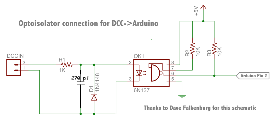
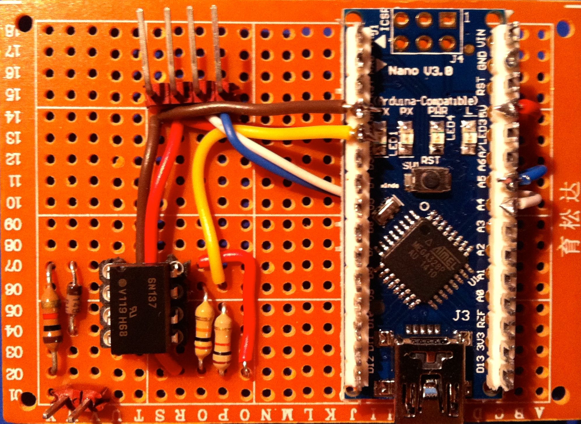
J’ai utilisé un simple Nano complété par un petit circuit d’interface entre les rails (tension +/- 15 volts, insupportable pour l’Arduino) et la broche 2 programmée en entrée digitale sous interruption.
Ce circuit est celui du site Minabay : j’y ai ajouté un condensateur de 270 pF (une valeur inférieure, jusqu’à 30-50 pF peut convenir également).
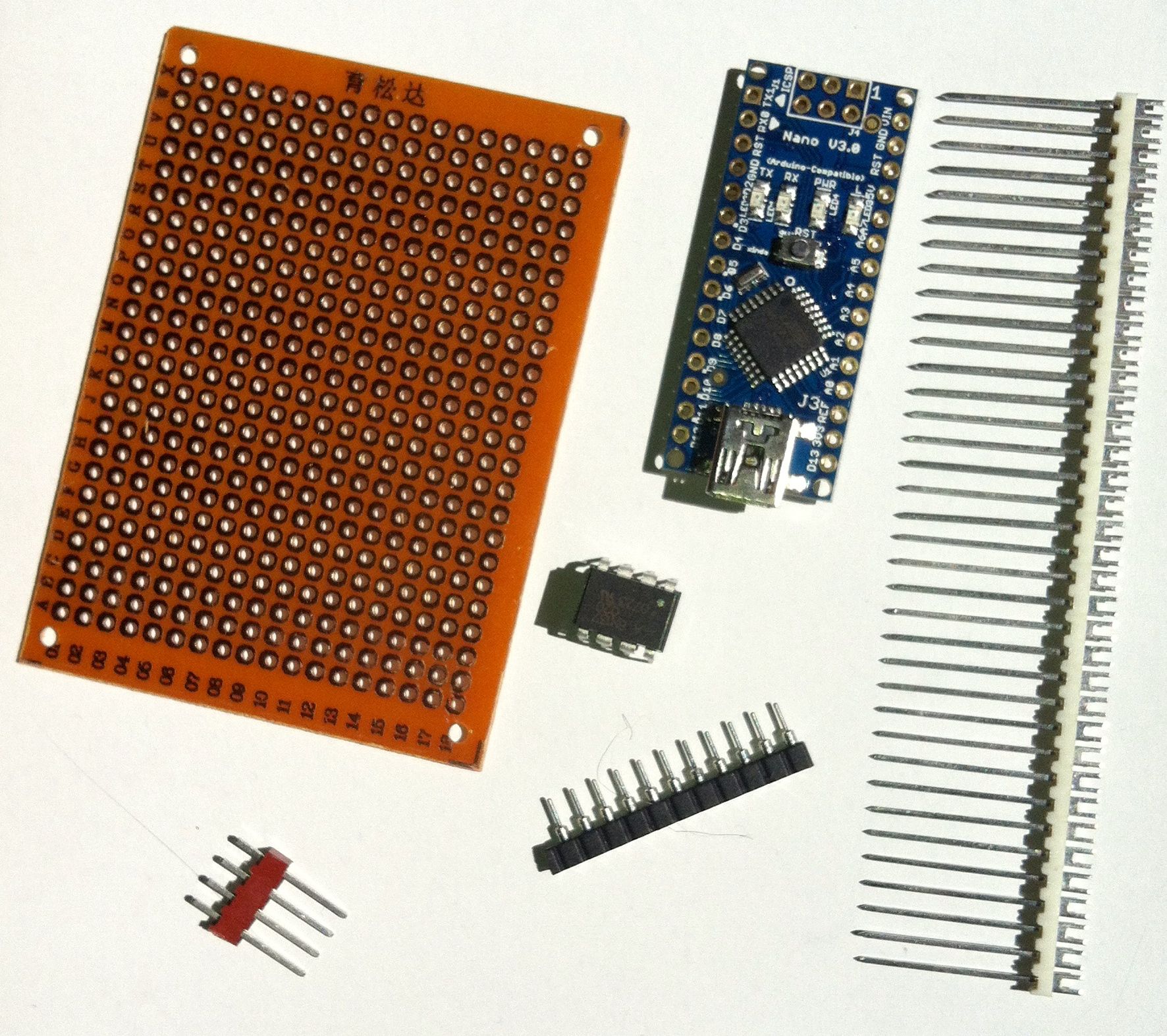
Voici la liste des composants nécessaires :
- un Arduino (j’ai choisi un Nano mais n’importe lequel doit convenir)
- 2 résistances de 10kΩ
- 1 résistance de 1kΩ
- 1 Diode 1N4148
- 1 condensateur de 270 picoFarad
- 1 Opto-coupleur 6N137 (il en faut un rapide quand même)
- 1 plaque d’essai pour assembler les composants
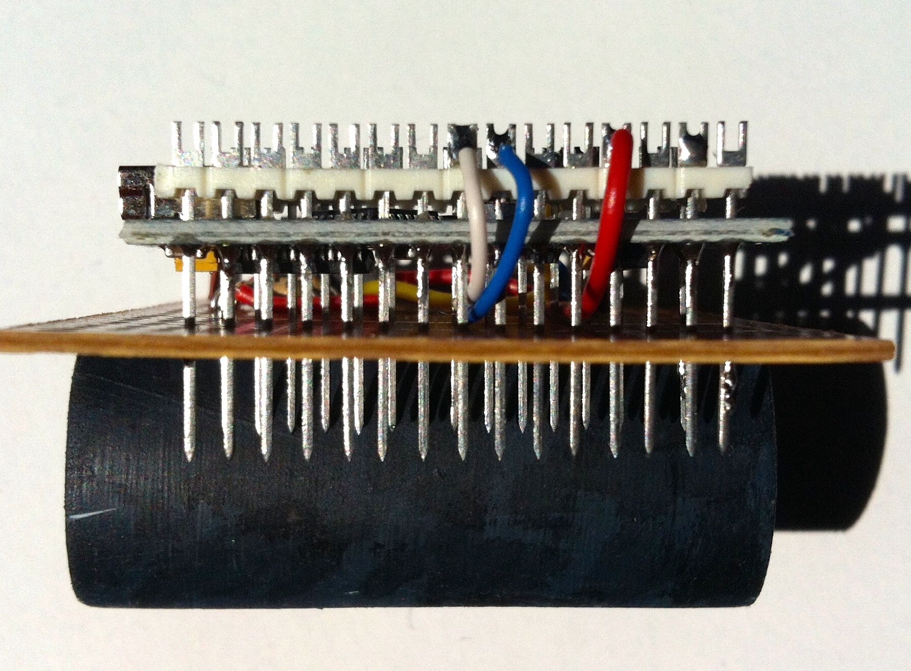
Plutôt que d’utiliser un Uno avec son bornier femelle, j’ai préféré le Nano sans bornier. J’ai inséré des barrettes à souder dans les trous à la place des barrettes à picots habituels : de cette façon les fils à raccorder au Nano sont soudés sur les barrettes ce qui procure un meilleur contact qu’un ensemble de prises mâle et femelle.
De ce fait, les barrettes du Nano ne sont soudées qu’aux 4 coins ce qui permet de récupérer l’Arduino si le projet n’est plus utilisé plus tard.
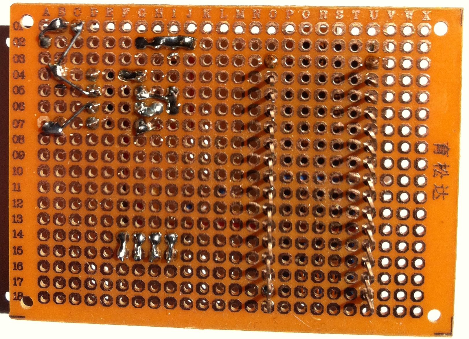
A l’arrière de la plaque d’essai, le nombre de soudures est minimal et on ne prend pas de risque da court-circuits.
Le circuit terminé ne m’a pris qu’une petite heure. Le connecteur 4 points permet de sortir une liaison I2C vers un afficheur LCD 4 lignes de 20 caractères qui devrait me permettre de me passer du PC/Mac, à condition d’ajouter une petite alimentation 5V. Pour la liaison I2C, ne pas oublier les 2 resistances de rappel au 5V, de 4,7kΩ chacune sur SDA et SDL respectivement.
Le logiciel qui suit ne tient pas compte de cette possibilité.
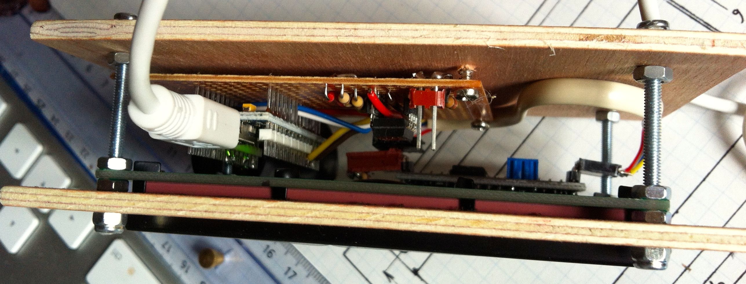
La mise en boite est un simple sandwich entre 2 planchettes de contreplaqué.
Le logiciel
Après installation de la bibliothèque, on ouvre simplement l’exemple DCC_Monitor qui se trouve dans le dossier DCC_Decoder.
// DCC_Monitor
// Based on DCC_Decoder Library Version 4
// Dump of DCC packets every 2 seconds
// Arduino Pin 2 is the DCC input. It drives interrupt 0.

#include <DCC_Decoder.h>

////////////////////////////////////////////////////////////////////////////////////////
////////////////////////////////////////////////////////////////////////////////////////
//
// Defines and structures
//
#define kDCC_INTERRUPT    0

typedef struct
{
    int count;
    byte validBytes;
    byte data[6];
} DCCPacket;

////////////////////////////////////////////////////////////////////////////////////////
////////////////////////////////////////////////////////////////////////////////////////
//
// The dcc decoder object and global data
//
int gPacketCount = 0;
int gIdlePacketCount = 0;
int gLongestPreamble = 0;

DCCPacket gPackets[25];

static unsigned long lastMillis = millis();

////////////////////////////////////////////////////////////////////////////////////////
////////////////////////////////////////////////////////////////////////////////////////
//
// Packet handlers
//

// ALL packets are sent to the RawPacket handler. Returning true indicates
// that packet was handled. DCC library starts watching for
// next preamble. Returning false and library continue parsing packet
// and finds another handler to call.
boolean RawPacket_Handler(byte byteCount, byte* packetBytes)
{
    // Bump global packet count
    ++gPacketCount;

    int thisPreamble = DCC.LastPreambleBitCount();
    if( thisPreamble > gLongestPreamble )
    {
        gLongestPreamble = thisPreamble;
    }

    // Walk table and look for a matching packet
    for( int i=0; i<(int)(sizeof(gPackets)/sizeof(gPackets[0])); ++i )
    {
        if( gPackets[i].validBytes )
        {
            // Not an empty slot. Does this slot match this packet?
            // If so, bump count.
            if( gPackets[i].validBytes==byteCount )
            {
                char isPacket = true;
                for( int j=0; j<byteCount; j++)
                {
                    if( gPackets[i].data[j] != packetBytes[j] )
                    {
                        isPacket = false;
                        break;
                    }
                }
                if( isPacket )
                {
                   gPackets[i].count++;
                   return false;
                }
            }
        }else{
                // Empty slot, just copy over data
            gPackets[i].count++;
            gPackets[i].validBytes = byteCount;
            for( int j=0; j<byteCount; j++)
            {
                gPackets[i].data[j] = packetBytes[j];
            }
            return false;
        }
    }

    return false;
}

// Idle packets are sent here (unless handled in rawpacket handler).
void IdlePacket_Handler(byte byteCount, byte* packetBytes)
{
    ++gIdlePacketCount;
}

////////////////////////////////////////////////////////////////////////////////////////
////////////////////////////////////////////////////////////////////////////////////////
//
// Setup
//
void setup()
{
    Serial.begin(9600);

    DCC.SetRawPacketHandler(RawPacket_Handler);
    DCC.SetIdlePacketHandler(IdlePacket_Handler);

    DCC.SetupMonitor( kDCC_INTERRUPT );
}

////////////////////////////////////////////////////////////////////////////////////////
////////////////////////////////////////////////////////////////////////////////////////
void DumpAndResetTable()
{
    char buffer60Bytes[60];

    Serial.print("Total Packet Count: ");
    Serial.println(gPacketCount, DEC);

    Serial.print("Idle Packet Count:  ");
    Serial.println(gIdlePacketCount, DEC);

    Serial.print("Longest Preamble:  ");
    Serial.println(gLongestPreamble, DEC);

    Serial.println("Count    Packet_Data");
    for( int i=0; i<(int)(sizeof(gPackets)/sizeof(gPackets[0])); ++i )
    {
        if( gPackets[i].validBytes > 0 )
        {
            Serial.print(gPackets[i].count, DEC);
            if( gPackets[i].count < 10 )
            {
                Serial.print("        ");
            }else{
                if( gPackets[i].count < 100 )
                {
                    Serial.print("       ");
                }else{
                    Serial.print("      ");
                }
            }
            Serial.println(
            	DCC.MakePacketString(
                    buffer60Bytes,
            	    gPackets[i].validBytes,
            	    &gPackets[i].data[0]
                )
            );
        }
        gPackets[i].validBytes = 0;
        gPackets[i].count = 0;
    }
    Serial.println("============================================");

    gPacketCount = 0;
    gIdlePacketCount = 0;
    gLongestPreamble = 0;
}

////////////////////////////////////////////////////////////////////////////////////////
////////////////////////////////////////////////////////////////////////////////////////
//
// Main loop
//
void loop()
{
    DCC.loop();

    if( millis()-lastMillis > 1000 )
    {
        DumpAndResetTable();
        lastMillis = millis();
    }
}
Une fois le programme compilé et installé dans l’Arduino, on relie l’interface aux rails, puis on lance le moniteur de l’environnement Arduino ou tout autre terminal de son choix.
J’ai testé le programme sur différents Arduino, y compris le Due.
Version LCD I2C
On trouve facilement, pour 10€ environ, des afficheurs 4 lignes de 20 caractères avec une interface I2C.
J’ai donc modifié l’exemple de Minabay ci-dessus pour obtenir un affichage décodé selon les besoins de mon projet (centrale va-et-vient).
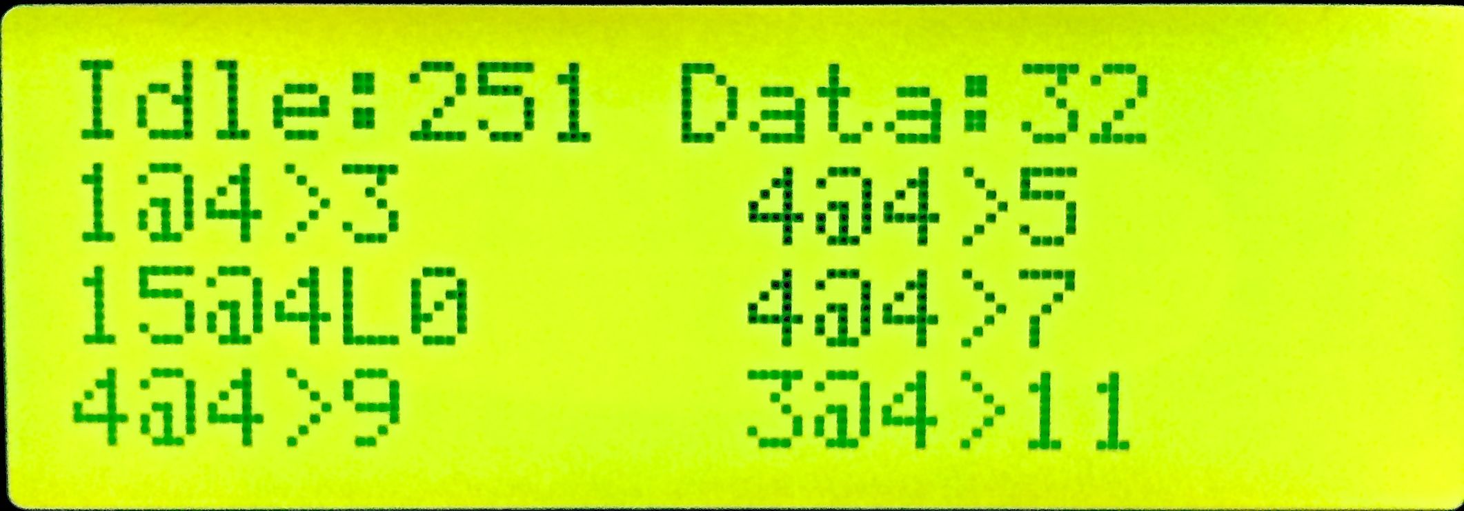
Toutes les 2 secondes, l’afficheur présente :
- Sur la ligne 1 : le nombre de paquets IDLE et le nombre de paquets de données valides ;
- Sur les lignes suivantes : le nombre de chaque type de paquet de données et leur signification.
Par exemple :
1@4>3 signifie 1 paquet d’adresse DCC 4, direction avant et vitesse 3
4@4>5 signifie 4 paquet d’adresse DCC 4, direction avant et vitesse 5
15@4L0 signifie 15 paquets d’adresse DCC 4, lumière éteinte
4@4>7 signifie 4 paquet d’adresse DCC 4, direction avant et vitesse 7
On voit bien l’accélération de 3 à 11 crans DCC pendant l’interval de 2 secondes.
Le logiciel de cette version est ici :
/*  DCC_Monitor for LCD 4x20

  Based on DCC_Decoder Library Version 4 from http://www.mynabay.com/arduino
  Display DCC packets counts every 2 seconds (IDLE should be around 50%)
  Arduino Pin 2 is the DCC input. It drives interrupt 0.
  Arduino Pin A4 is SDA, Pin A5 is SLC (even on Nano !).
  To connect an LCD 20x4 display via I2C

  Don't forget I2C pull-up resistors (4,7K each) connected to + 5V
  Compilation on Arduino 1.5.x necessitate a minor change in the DCC_Decoder library:
  Replace "prog_char*" type by "char*"

  Display 1st line : Idle paquets count, valid data paquets count
  Display next lines : for each data type :
  - paquet count, DCC address,
    - speed paquet : direction (< or >), speed value (0..127)
    - light function paquet (FL) : L0 (off) or L1 (on)

  This program is free software; you can redistribute it and/or
  modify it under the terms of the GNU General Public License
  as published by the Free Software Foundation.

  Copyright (c) 2014 Dominique Bultez. */

#define VERSION "1.0b3 Oct 14"
#define D_USB // comment this line to cancel display to the computer's terminal

#include <DCC_Decoder.h>
#include <Wire.h>
#include <LiquidCrystal_I2C.h>

LiquidCrystal_I2C lcd(0x27,20,4);  // set the LCD address to 0x27 for a 20 chars and 4 line display

////////////////////////////////////////////////////////////////////////////////////////
//
// Defines and structures
//
#define kDCC_INTERRUPT            0

typedef struct
{
    int count;
    byte validBytes;
    byte data[6];
} DCCPacket;

////////////////////////////////////////////////////////////////////////////////////////
//
// The dcc decoder object and global data
//
int gPacketCount = 0;
int gIdlePacketCount = 0;
int gLongestPreamble = 0;

DCCPacket gPackets[25];

static unsigned long lastMillis = millis();

////////////////////////////////////////////////////////////////////////////////////////
//
// Packet handlers
//

// ALL packets are sent to the RawPacket handler. Returning true indicates
// that packet was handled. DCC library starts watching for
// next preamble. Returning false and library continue parsing packet
// and finds another handler to call.
boolean RawPacket_Handler(byte byteCount, byte* packetBytes)
{
        // Bump global packet count
    ++gPacketCount;

    int thisPreamble = DCC.LastPreambleBitCount();
    if( thisPreamble > gLongestPreamble )
    {
        gLongestPreamble = thisPreamble;
    }

        // Walk table and look for a matching packet
    for( int i=0; i<(int)(sizeof(gPackets)/sizeof(gPackets[0])); ++i )
    {
        if( gPackets[i].validBytes )
        {
                // Not an empty slot. Does this slot match this packet? If so, bump count.
            if( gPackets[i].validBytes==byteCount )
            {
                char isPacket = true;
                for( int j=0; j<byteCount; j++)
                {
                    if( gPackets[i].data[j] != packetBytes[j] )
                    {
                        isPacket = false;
                        break;
                    }
                }
                if( isPacket )
                {
                   gPackets[i].count++;
                   return false;
                }
            }
        }else{
                // Empty slot, just copy over data
            gPackets[i].count++;
            gPackets[i].validBytes = byteCount;
            for( int j=0; j<byteCount; j++)
            {
                gPackets[i].data[j] = packetBytes[j];
            }
            return false;
        }
    }

    return false;
}

// Idle packets are sent here (unless handled in rawpacket handler).
void IdlePacket_Handler(byte byteCount, byte* packetBytes)
{
    ++gIdlePacketCount;
}

////////////////////////////////////////////////////////////////////////////////////////
//
// Setup
//
void setup()
{
   Serial.begin(115200);
   lcd.init();                      // initialize the lcd
   lcd.backlight();

   lcd.print("DCC monitor Version ");
   lcd.print(VERSION);
   delay(1000);
   //lcd.clear();

   DCC.SetRawPacketHandler(RawPacket_Handler);
   DCC.SetIdlePacketHandler(IdlePacket_Handler);

   DCC.SetupMonitor( kDCC_INTERRUPT );
}

////////////////////////////////////////////////////////////////////////////////////////
void DumpAndResetTable()
{
    char buffer60Bytes[60];

    #ifdef D_USB
    Serial.print("Total Packet Count: ");
    Serial.println(gPacketCount, DEC);
    #endif

    lcd.clear();
    //lcd.setCursor(0, 0);    // 1e ligne
    lcd.print("Idle:");
    lcd.print(gIdlePacketCount, DEC);

    #ifdef D_USB
    Serial.print("Idle Packet Count:  ");
    Serial.println(gIdlePacketCount, DEC);
    #endif

    lcd.print(" Data:");
    lcd.print(gPacketCount - gIdlePacketCount, DEC);
    lcd.print("  ");

    #ifdef D_USB
    Serial.print("Longest Preamble:  ");
    Serial.println(gLongestPreamble, DEC);
    Serial.println("Count    Packet_Data");
    #endif

    lcd.setCursor(0, 1);    // 2e ligne
    int j=0;
    for( int i=0; i<(int)(sizeof(gPackets)/sizeof(gPackets[0])); ++i )
    {
        if( gPackets[i].validBytes > 0 )
        {
            if (gPackets[i].count != gIdlePacketCount)
            {
              #ifdef D_USB
              Serial.print(gPackets[i].count, DEC);
              if( gPackets[i].count < 10 )
              {
                Serial.print("        ");
              }else{
                if( gPackets[i].count < 100 )
                {
                    Serial.print("       ");
                }else{
                    Serial.print("      ");
                }
              }
              Serial.println(
                  DCC.MakePacketString(
                      buffer60Bytes,
                      gPackets[i].validBytes,
                      &gPackets[i].data[0]
                  )
              );
              #endif

              if (gPackets[i].data[0] != 255)
              {
                lcd.print(gPackets[i].count, DEC);
                lcd.print("@");
                lcd.print(gPackets[i].data[0], DEC);
                switch (gPackets[i].data[1])
                {
                  case 0x3F:  // Advanced Operation Instruction : speed & direction
                  if (gPackets[i].data[2] > 127)
                  {
                    lcd.print(">");
                    lcd.print(gPackets[i].data[2] - 128);
                  }else{
                    lcd.print("<");
                    lcd.print(gPackets[i].data[2]);
                  }
                  break;
                  case 0x90:  // Fonction Group One FL on
                  lcd.print("L1");
                  break;
                  case 0x80:  // Fonction Group One FL off
                  lcd.print("L0");
                  break;
                  default:
                  lcd.print(gPackets[i].data[1], HEX);
                  break;
                }
                j++;
                if (j>5) j=0;
                switch (j)
                {
                  case 0:
                  lcd.setCursor(0, 1);    // 2e ligne
                  break;
                  case 1:
                  lcd.setCursor(10, 1);    // 2e ligne
                  break;
                  case 2:
                  lcd.setCursor(0, 2);    // 2e ligne
                  break;
                  case 3:
                  lcd.setCursor(10, 2);    // 2e ligne
                  break;
                  case 4:
                  lcd.setCursor(0, 3);    // 2e ligne
                  break;
                  case 5:
                  lcd.setCursor(10, 3);    // 2e ligne
                  break;
                }
              }
            }
        }
        gPackets[i].validBytes = 0;
        gPackets[i].count = 0;
    }
    #ifdef D_USB
    Serial.println("============================================");
    #endif

    gPacketCount = 0;
    gIdlePacketCount = 0;
    gLongestPreamble = 0;
}

////////////////////////////////////////////////////////////////////////////////////////
//
// Main loop
//
void loop()
{
    DCC.loop();

    if( millis()-lastMillis > 2000 )
    {
        DumpAndResetTable();
        lastMillis = millis();
    }
}
Le code peut être téléchargé ici :
La bibliothèque peut être téléchargée ici :
Dernièrement j’ai ajouté un circuit d’alimentation à partir des rails : il contient un pont redresseur reliée au connecteur des rails et suivi d’une capacité de 22uF, puis d’un régulateur 7805 et d’une capacité de 100uF. La sortie est reliée directement au 5V de l’Arduino.